In the world of VLSI chip design, Physical Design (PD) is the stage where a logical circuit is transformed into a physical layout ready for fabrication. But before this process begins, several critical input files are required to guide the tools and ensure accurate implementation. In this article, we will discuss the important input files required to start the Physical Design implementation.
1. Netlist
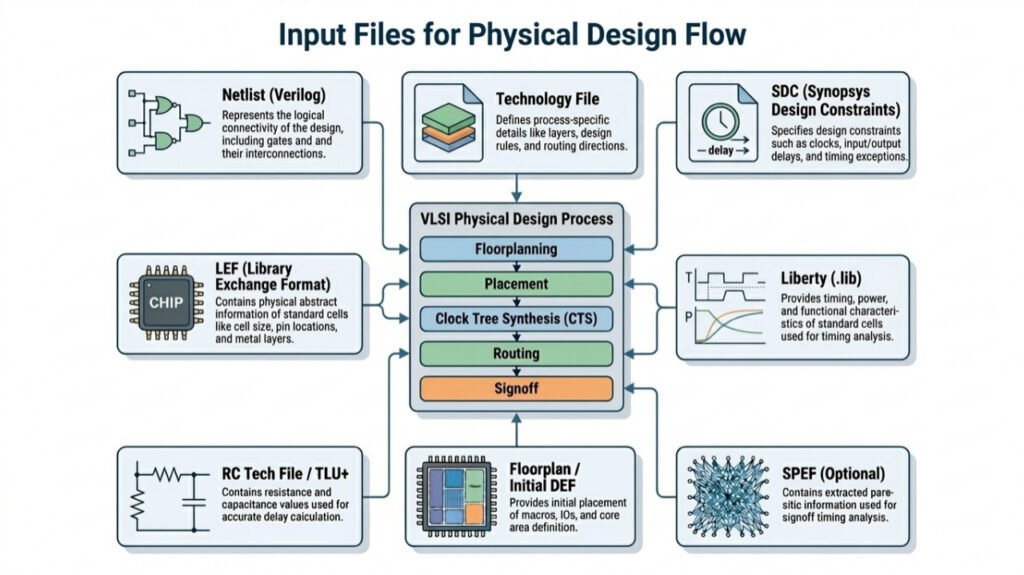
A netlist is a text file that describes the logical connectivity of the entire design, usually written in Verilog (.v format). It contains the list of standard cells such as AND, OR, and Flip-Flops, along with their instances, the connections between them, and the input/output ports that define how the design interacts with the external world.
2. Library Exchange Format (.lef)
LEF provides an abstract representation of the physical properties of standard cells and macros, describing key details such as their dimensions (width and height), the precise locations of pins used for connectivity, information about the metal layers that guide routing, and any routing blockages that define restricted regions where wires cannot be placed.
3. Liberty File (.lib)
The Liberty file provides a comprehensive description of the timing, power, and functional behaviour of standard cells, including parameters such as propagation delays, setup and hold timing requirements, power consumption characteristics, output transition details, and capacitance values required for accurate timing and power analysis across different operating conditions.
4. Design Exchange Format (DEF)
DEF captures the physical implementation of the design by including detailed information about cell placement locations, routing paths that define how different components are connected, floorplan specifications such as core boundaries and regions, and via definitions used to establish connections between different metal layers.
5. Synopsys Design Constraints (SDC)
The SDC file defines the timing and design constraints that guide the entire Physical Design flow, including clock definitions, input and output delays, false paths, multicycle paths, and various timing exceptions that instruct the tools on how to optimize the design for performance, timing closure, and functional correctness.
6. Technology File (.tf/.techlef)
The technology file contains detailed process-specific information required for physical implementation, including available metal layers, design rules such as spacing and width constraints, preferred routing directions for each layer, and via definitions, ensuring that the design complies with manufacturing and foundry requirements.
7. RC Tech File (tluplus)
The RC technology file provides detailed resistance and capacitance data for different metal layers and routing conditions, enabling accurate modeling of interconnect parasitics, which is essential for precise delay calculation, timing analysis, and signal integrity evaluation.
8. SPEF File
The SPEF file contains detailed parasitic extraction data generated after routing, including net resistance, ground capacitance, and coupling capacitance values, which are used during signoff timing analysis to accurately reflect real interconnect delays and validate the final performance of the design.
9. MMMC File (Multi-Mode Multi-Corner)
MMMC helps us to check whether our design works correctly under different real-world conditions. It does this by defining multiple operating modes, like functional and test modes and different PVT corners such as slow, fast, and typical corners. It also includes the required timing libraries, RC conditions, and constraint sets for each case, so the tool can analyze and optimize the design across all these scenarios and ensure it is reliable in every situation.
If you want to learn about “What is Synthesis” click here.

Pingback: What is Synthesize in Physical Design?